· Riley Prentice · Projects · 5 min read
Dave the Autonomous Whiteboard Eraser
Autonomous Instructional-Surface Cleaning Unit
A Messy Whiteboard Problem
All classrooms share a common problem: a lack of directly cleaning the whiteboard after use leaves marks that can remain for months. Especially in our engineering labs where there are constantly calculations, layouts, and just general lists that get written down throughout the day.
The Bradley University D.A.W.E. team set out to solve this issue.
Links:
System Block Diagram
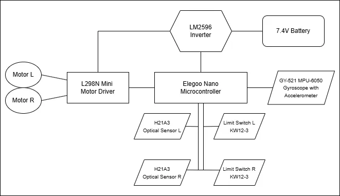
The Bradley University D.A.W.E. robot follows the same format as a typical PWM driven device. The microcontroller chosen was an Arduino Nano. It was selected over the Arduino Uno because of its smaller size while still having the same number of output pins, 14 digital and eight analog.
If this project were to be recreated but with additional features, it may require a more specialized microcontroller as we only have five digital pins and six analog pins left on the Nano.
Control
ELEGOO Nano Board with ATmega 328P CH340 Chip
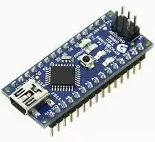
The Elegoo Nano acts as the brain of the robot. A combination of the 14 digital pins and eight analog pins send signals to the different components of the robot. The Arduino Nano was chosen due to its small size and weight which is a crucial part of this project if it is to successfully adhere to the whiteboard.
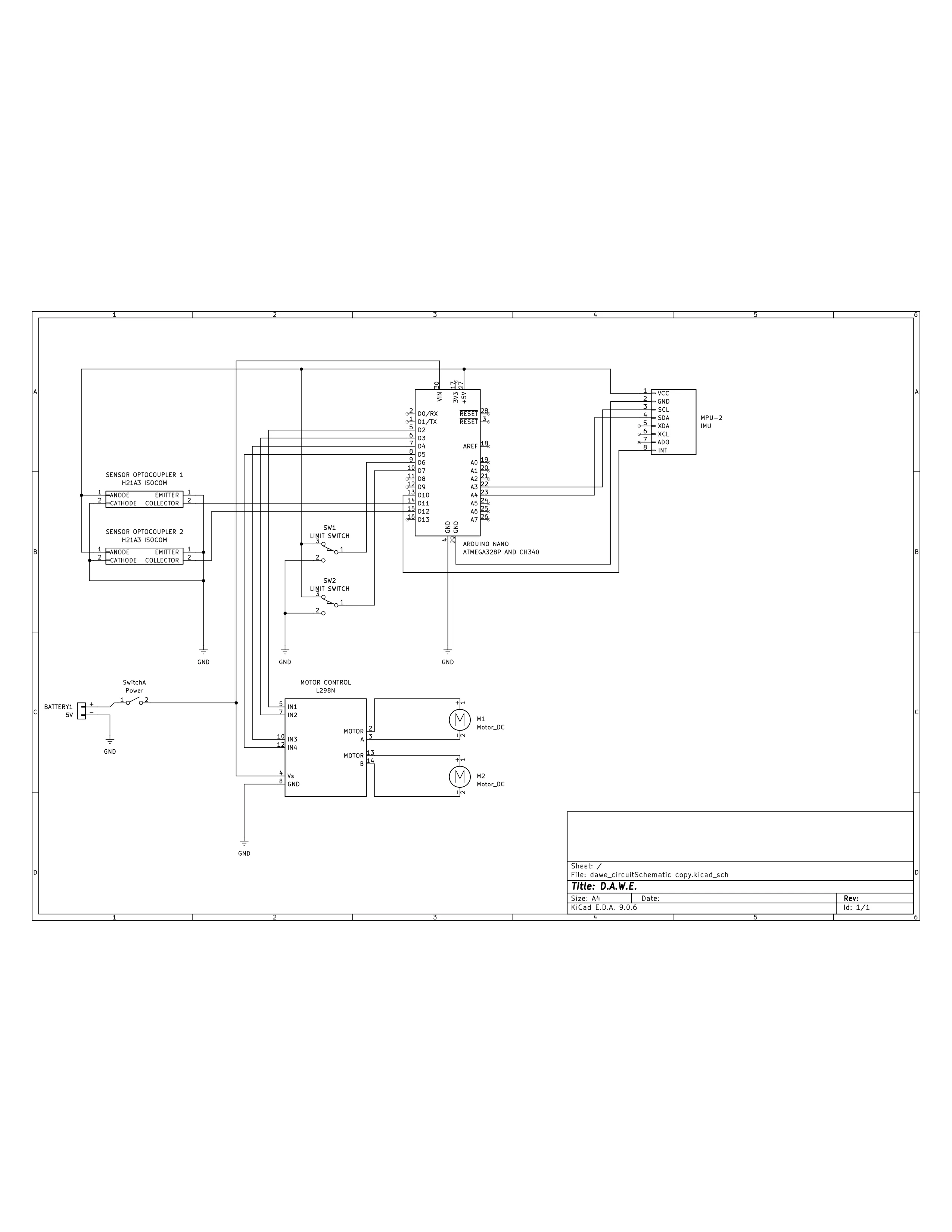
With the current layout there are five unused digital pins and six analog pins remaining for other additions.
Navigation
A large part of the project is board navigation. To address this, we created two modes. The first one is a simple square design, the robot navigates two feet up and three feet to the left, erasing everything within those dimensions. If the entire board needs to be cleaned, the secondary mode is available: the robot navigates around the outer edge of the board to manually detect the size, then it erases everything within that size.
Sensors
To navigate the board, the robot relies on three sensors.
KW12-3 Microswitch

The Kw12-3 microswitch is made by Soldered and is a simple limit switch that sends a signal to the microcontroller. The other inputs are for 5V and ground.
GY-521 MPU-6050 Gyroscope with Accelerometer
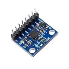
The GY-521 MPU-6050 is a gyroscope with accelerometer and is used to sense the direction and orientation of the robot. An additional feature exists to calculate the distance the robot has traveled, but this went unused due to its inaccuracy. Instead, the data from the gyroscope is used to tell the orientation of the robot. Then, the acceleration is used to sense if the robot is sliding down the board. It would either show zero if it it was decelerating while going up or if the acceleration increases while going down. This is important because it is expected that the robot runs into traction issues later in development.
H21A3 Optical Sensor
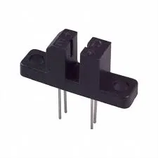
The H21A2 Optical Sensor is used in corelation with the photo interrupter disks mounted on the motors as a custom encoder to manage the amount of revolutions the motor has made. This data is then used to calculate the distance the the robot has traveled.
Power
All of the robot relies on a 5V power source.
Battery

The battery on the robot is a Urgenex Li-ion 7.4V 20000mAh battery which is connected to a power switch, then to the inverter.
Inverter
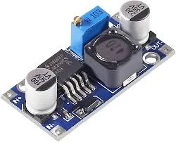
The inverter is a LM2596 DC to DC power inverter. It steps the voltage down from 7.4V to the 5V that the robot operates on.
Movement
There are two parts to make the robot move: the motors and the motor controllers.
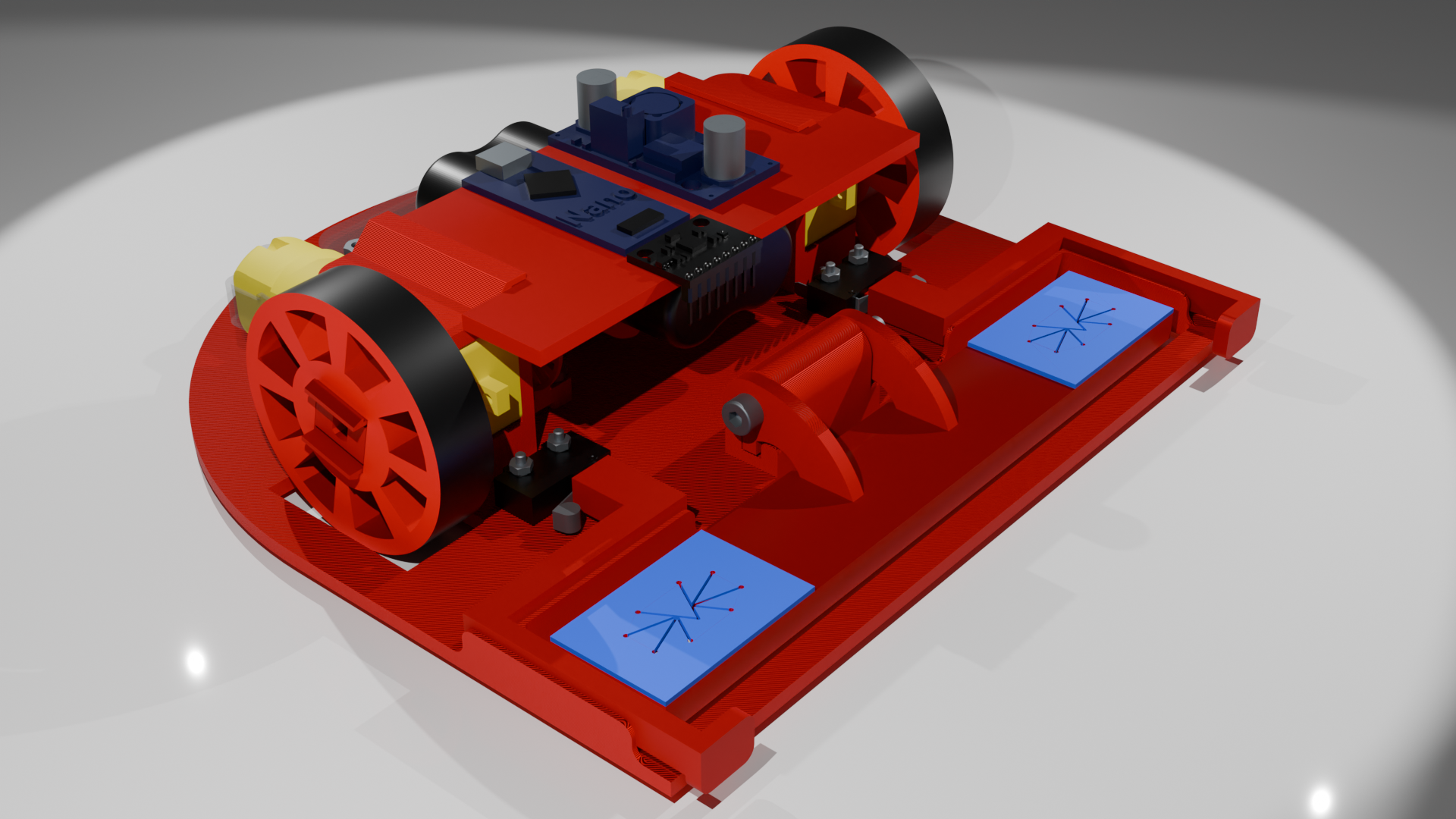
Mini L298N Motor Driver
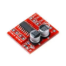
The Mini L298N motor driver takes four inputs and the power to move the motors. This motor driver uses two pins per motor that use the PWM signal generated by the microcontroller and the power input from the inverter to control the motor speed. The motors are directly mounted to the output pins of the motor controller.
DC Gearbox Motor
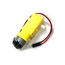
The DC gearbox motor is a simple 3V-6V motor with an attached 1:48 reduction gearbox. These are used to move the wheels. Each motor has a positive and negative wire which go to the corresponding terminal on the motor controller. One side of the motor shaft connects to the wheel hub and the other attaches to the photo interrupter disk for the optical sensor.
Frame
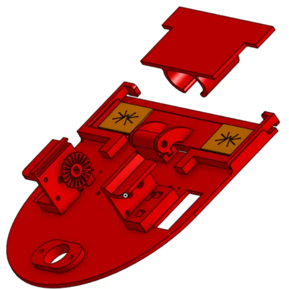
The main chassis of the robot is CAD designed and 3D printed. It was developed specifically to work with the chosen components on the robot. The frame was printed with Polylactic Acid (PLA) Filament on a Prusa MK4S. The Frame can be better viewed by going to the attached OnShape file.
Cost
This project uses hobbyist-grade technologies, meaning that the project is relatively cheap. As of Q4 2025, the cost of one unit is $29.31, not including the filament for the frame. It is worth noting that the project is still under development and as a result the cost is not yet finalized.
Potential Improvements
- Develop AI system so that the robot only cleans the necessary/specified areas.
- Include a docking station for the robot to stay idle and recharge.
- Have a liquid cleaning solution dispensing system if the eraser alone is not adequate.
- Design and integrate a through-hole printed circuit board to improve component layout.